

An Onsite Wastewater Treatment System Owner’s Manual
Diagram of System
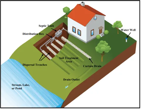
To receive the best performance from your system, it is essential to know what type of ONSITE WASTEWATER TREATMENT SYSTEM you have, where it is located, and its basic OPERATION and MAINTENANCE requirements. A diagram of your system is a key component in understanding your system.
- Show property lines and dimensions to reflect the shape and size of the property.
- Diagram proposed or existing ONSITE WASTEWATER TREATMENT SYSTEM. Show appropriate elevations to indicate proper fall for the system.
- Show distances to the house, well, water lines, property lines, and geological features such as sinkholes, rock outcrops, lakes, ponds, streams, and rivers.
- Show distances to neighbors’ wells, homes, and sewage systems.
- Use arrows to indicate the direction of slope.
- Indicate any known easements that exist for utilities, roads, private driveways, or other easements.
- If applicable, show the location of a curtain drain or interceptor drain.
- If applicable, show locations of all percolation test holes or soil morphology test pits.
- If applicable, show fence location around the lagoon (waste stabilization pond).

| Item | Minimum Setback Distances (in feet) | Sewage Tank | Soil Treatment System | Lagoons |
|---|---|---|---|---|
| A | Private Well | 50 | 100 | 100 |
| B | Classified Stream, Lake, or Pond | 50 | 50 | 50 |
| C | Property Lines | 10 | 10 | 75* |
| D | Residential Foundation | 5 | 15 | 100 |
| E | Residential Basement Foundation | 15 | 25 | 100 |
| F | Upslope Interceptor Drains | - | 10 | 10 |
NOTE: *100 feet from Lagoons Overflow.
NOTE: Not all setback distances are shown above. A complete listing can be found in 19 CSR 20-3.060,
Table 1: Minimum Setback Distances.